
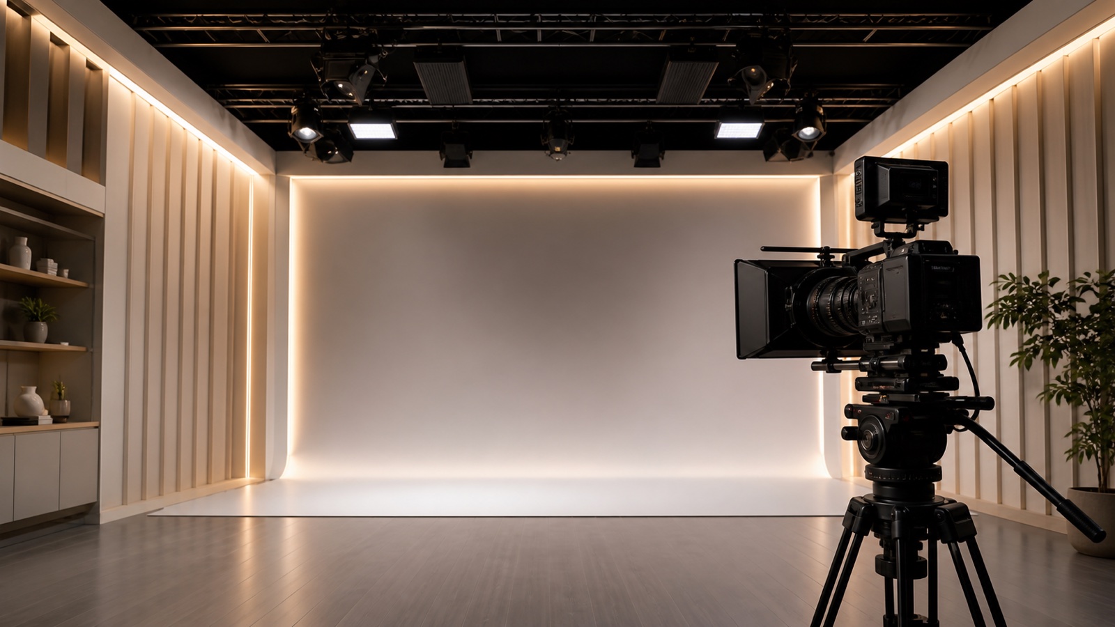
LED strip lights can look perfectly steady to the eye and still produce dark bands, rolling bars, pulsing brightness, or uneven color on camera. For a livestream studio, product-video set, retail display, museum installation, showroom, broadcast background, or content-creation space, that is not a minor visual defect. It can force a reshoot, restrict camera settings, or require the lighting system to be replaced after installation.
The correct purchasing question is not simply, "Is this LED strip flicker-free?"
It is:
Has the complete LED strip, power supply, dimmer or controller, wiring, and camera setup been tested at the frame rates, shutter settings, colors, and dimming levels required by the project?
This guide explains why LED strip lights flicker on camera and how B2B buyers should specify, sample, and approve a camera-compatible LED strip system.
1. Quick answer: what should buyers specify?
For filmed environments, treat flicker performance as a system requirement rather than a strip-only specification.
| Purchasing checkpoint | What to request |
|---|---|
| Camera conditions | Camera model, frame rate, shutter speed or shutter angle, sensor mode, and any slow-motion requirement. |
| Dimming method | Non-dimmed, analog/constant-current reduction, PWM, or hybrid dimming. |
| PWM performance | Actual output PWM frequency, whether it is fixed or adjustable, and performance at low dimming levels. |
| Power supply | Regulated constant-voltage output, correct load range, compatible dimming interface, and low optical modulation in the assembled system. |
| Strip electrical data | Constant-voltage or IC-based architecture, voltage, W/m, current per meter, channel type, cut interval, maximum supported run, and power-feed plan. |
| Light quality | CCT, CRI, R9, color consistency, and, where relevant, TLCI or a spectral test report. |
| Sample evidence | On-camera test using the real strip length, power supply, controller, wiring, and intended camera settings. |
For standard video work, a documented high-frequency PWM controller or a well-designed non-PWM dimming route is a better starting point than an unspecified controller. Camera-oriented professional products commonly use PWM around 20-25 kHz or higher, but no single frequency guarantees clean results for every camera, shutter speed, dimming level, or high-speed mode. Final approval should come from a project-specific sample test.
2. Why an LED strip can flicker on camera but not to the eye
LEDs respond very quickly to changes in electrical current. If the driver or dimmer varies that current over time, the light output follows the waveform closely. Human vision may average the changes into apparently steady light, while a camera samples the scene in shorter time intervals and can record the modulation.
Three mechanisms matter most.
PWM dimming
Pulse-width modulation, or PWM, controls average brightness by switching the LEDs on and off rapidly. At a lower dimming level, the on-time becomes shorter relative to the off-time. If the camera exposure does not average enough PWM cycles, the image may show bands or brightness changes.
Driver or power-supply ripple
Even without an external dimmer, a power supply can leave periodic ripple in its DC output. Mains-related modulation may appear around 100 Hz in 50 Hz regions or 120 Hz in 60 Hz regions after full-wave rectification, although the actual optical waveform depends on the power-supply design and the complete load. A better regulated supply reduces this risk, but the optical output of the assembled system still needs to be checked.
Camera shutter and sensor readout
Many cameras use a rolling shutter: different sensor rows are exposed at slightly different times. If the LED output changes during that readout, some rows receive more light than others, creating horizontal bands. A mismatch across successive frames can also appear as whole-frame pulsing or moving bars.
This is why the same LED system may look clean at 25 fps and 1/50 second but show banding at 120 fps or 1/1000 second. It is also why a test on one phone does not prove compatibility with a cinema camera, industrial camera, or another sensor mode.
3. PWM frequency is important, but frequency alone is not enough
PWM frequency describes how many switching cycles occur each second. A useful first-order check is:
Cycles captured during one exposure = PWM frequency x exposure time
For example:
- At 500 Hz PWM and a 1/1000-second exposure, the exposure covers only 0.5 PWM cycle.
- At 25 kHz PWM and the same 1/1000-second exposure, it covers 25 cycles.
The second condition gives the camera much more opportunity to average the light output. However, this calculation is only a screening tool. Rolling-shutter timing, modulation depth, duty cycle, controller behavior, color-channel timing, and the exact waveform can still affect the result.
When reviewing a supplier specification, ask for all of the following:
- PWM frequency in hertz or kilohertz
- whether the frequency is fixed, selectable, or changes by mode
- dimming range and minimum stable level
- output waveform or optical flicker measurement at several dimming levels
- test conditions used for any "flicker-free" or "camera-ready" claim
- performance for every channel used in CCT, RGB, RGBW, or addressable products
A controller described only as "high frequency" is not a complete specification.
4. What "flicker-free" does and does not mean
The lighting industry uses several flicker-related measurements, including flicker percentage, flicker index, PstLM, and SVM. These are useful for characterizing temporal light modulation and human visual effects. IEEE 1789 also addresses health risks associated with modulated LED light.
These metrics should not automatically be treated as a camera-compatibility certificate. A product can meet a human-vision requirement and still produce camera artifacts at a fast shutter speed or high frame rate. The U.S. Department of Energy specifically notes that a metric intended for an average observer cannot predict the response of a video camera.
For procurement, a credible camera-related claim should state:
- the complete tested lighting configuration
- camera model and sensor mode
- frame rate
- shutter speed or shutter angle
- brightness setting
- CCT or color-channel setting
- test distance and exposure conditions
- whether the result was checked for static bands, moving bands, pulsing, and color variation
Without these conditions, "flicker-free" is a marketing phrase rather than a project acceptance criterion.
5. The strip, power supply, and controller must be selected together
Most low-voltage LED strips are only the light-emitting load. Their on-camera performance depends heavily on the electronics that power and dim them.
| Component | Camera risk | What to confirm |
|---|---|---|
| LED strip | Electrical loading, color quality, heat, voltage drop, and channel structure. | Voltage, W/m, run length, CCT, CRI/R9, PCB width, and whether it is single-color, CCT, RGB/RGBW, or addressable. |
| Power supply | Output ripple, load compatibility, regulation, and dimming behavior. | Rated voltage, usable load range, output ripple data, dimming interface, and compatibility with the controller. |
| PWM dimmer / controller | Switching frequency, duty cycle, resolution, minimum level, and channel timing. | Actual PWM frequency, selectable modes, dimming curve, low-level behavior, and per-channel performance. |
| Wiring and feed plan | Voltage drop, unstable connections, or overload can create brightness variation unrelated to normal PWM. | Cable size, feed points, maximum run, connector current rating, and measured voltage at the far end. |
| Camera | Frame rate, shutter, rolling-shutter readout, anti-flicker functions, and exposure mode. | The actual production settings, not a generic phone test. |
Use the real planned strip length during sampling. A 30 cm sample on a bench may behave differently from a long installed run that operates near the power-supply limit or suffers voltage drop.
6. Does COB, SMD, 12V, 24V, or high CRI determine camera flicker?
COB vs SMD
COB can create a smoother, dotless line, while SMD offers broad package, density, color, and output options. Neither structure is inherently camera-safe. If both are controlled by the same low-frequency PWM dimmer, both can show camera banding.
Choose COB when the visible line must look continuous. Choose SMD when package choice, output range, color options, or serviceability is more important. Then validate the selected control system separately.
12V vs 24V
Voltage does not by itself determine flicker. A 24V strip often supports better voltage-drop control over comparable runs, but it can still flicker if the power supply or dimmer produces problematic modulation. Select voltage from run length, cut interval, current, and power-distribution needs, not from an unsupported camera-flicker assumption.
High CRI and full spectrum
High CRI, R9, TLCI, and spectral quality address how colors are rendered. Flicker describes how light output changes over time. A high-CRI strip can still flicker, and a low-flicker strip can still render skin tones or products poorly.
For filmed retail, museum, product-display, interview, and livestream scenes, buyers should specify both:
- temporal performance for the camera; and
- color performance for the subject.
Wismart's High CRI / Full Spectrum SMD series includes confirmed 24V CRI 98 options. That makes it a relevant color-quality route for sample evaluation, but CRI 98 is not a camera-flicker claim. It should be paired with a specified power supply and controller, then tested as a complete system.
7. Which LED strip specifications reduce camera-flicker risk?
The strip still matters, even though it cannot guarantee camera compatibility by itself. Its electrical architecture, load, run length, channel structure, optical construction, and thermal behavior determine what the power supply and controller must drive and what the camera will see.
Start by identifying where brightness modulation is generated. A conventional constant-voltage single-color, tunable-white, or RGB/RGBW strip is commonly a load made from LED-and-resistor segments, with dimming produced by an external driver or controller. By contrast, an addressable or IC-regulated strip may contain onboard electronics with their own PWM, refresh, scan, or current-control behavior. Do not assume that the external controller's frequency describes an IC-based strip's complete optical waveform.
Direct purchasing recommendation
For a fixed-white interview, livestream, product-video, retail, or museum installation, the lower-risk strip-side starting point is usually:
- a conventional passive constant-voltage strip without an onboard low-frequency pixel PWM or scanning system;
- fixed white if color changing is not required, because one light channel is simpler to qualify than several independently modulated channels;
- 24V for medium or longer runs when it improves the current and feed design, or 12V when the project needs its cut interval or uses short runs;
- documented W/m, current per meter, maximum run, cut interval, PCB width, and feed requirements;
- a regulated constant-voltage power supply selected for the actual load;
- no dimming, a validated non-PWM route, or a controller with a documented output around 20-25 kHz or higher at every required dimming level; and
- an optical-waveform check plus an on-camera test using the actual strip length, supply, controller, wiring, frame rate, shutter, color, and brightness range.
This is a procurement starting point, not a universal pass certificate. A passive strip on clean continuous DC is easier to characterize because it has no intentional onboard PWM, but power-supply ripple can still modulate its light. A 24V strip can improve current distribution but does not suppress PWM. A 25 kHz system may work well for normal production and still fail under an unusually short exposure or high-speed camera mode.
Camera-oriented parameter priority
| Priority parameter | Lower-risk starting specification | What to avoid or verify |
|---|---|---|
| Onboard modulation | Passive constant-voltage strip with no onboard PWM/scan when fixed or externally controlled light is acceptable. | If the strip contains a pixel or current-control IC, obtain its optical PWM/refresh frequency, mode behavior, and test evidence. |
| Dimming frequency | No intentional PWM, validated non-PWM dimming, or documented PWM around 20-25 kHz or higher for normal video as a starting point. | Reject an unspecified "high-frequency" claim. Confirm that frequency does not fall or enter burst/pulse-skipping behavior at low output. |
| Channel structure | Fixed-white, single-channel strip when color changing is unnecessary. | For tunable white, RGB, RGBW, or addressable products, verify every channel, mixed color, fade, and low-level condition. |
| Voltage | 24V for medium or long runs when lower current improves distribution; 12V for short runs or when its cut interval better fits the layout. | Do not treat 12V or 24V as a temporal-flicker rating. Test the intended run and feed plan. |
| Electrical load | Documented W/m, current per meter, tolerance, total length, and maximum run. | Do not approve a 30 cm strip sample and then assume identical behavior at a much larger driver load. |
| Full-output behavior | With the matched controller, confirm whether 100% output becomes continuous DC or remains modulated. | Do not assume full brightness is automatically clean; check supply ripple and actual optical output. |
| Low-level behavior | Stable waveform, frequency, and channel timing at the lowest brightness the project will use. | Check 50%, 25%, 10%, and the real minimum level for bands, pulsing, pulse skipping, stepping, and color separation. |
| Test evidence | Optical waveform and camera results tied to the exact strip, supply, controller, firmware, load, and camera settings. | PstLM, SVM, CRI, a phone-only test, or an unsupported "flicker-free" label is not sufficient camera evidence. |
How to interpret PWM frequency in an RFQ
The following is a screening guide, not a universal pass/fail standard:
| Reported behavior | Camera-oriented purchasing interpretation |
|---|---|
| Continuous DC with no intentional PWM | Strong starting point if optical ripple from the power supply is also low and low-level/color performance is acceptable. Still verify on camera. |
| Around 20-25 kHz or higher | Preferred starting range for ordinary professional video and photography. Confirm the value at every dimming level and channel, then test the fastest required shutter. |
| A few kilohertz | May work for some normal settings but should not be approved from frequency alone. Fast shutter, rolling-shutter timing, deep dimming, or high-speed modes may still show bands. |
| Hundreds of hertz to approximately 1-2 kHz | Higher camera-artifact risk, especially with short exposures. Human-visible flicker compliance does not prove camera compatibility. |
| 100/120 Hz or mains-related ripple | High risk for banding or frame-to-frame brightness changes when shutter timing is not synchronized. Improve the power/control system or restrict and validate camera settings. |
| Frequency not stated | Insufficient for a camera-critical RFQ. Request a numerical frequency, waveform, modulation depth, duty-cycle behavior, and test conditions. |
If a supplier quotes one frequency, ask where it was measured: at the dimming input, controller output, strip current, or optical output. The optical waveform is the most relevant evidence because protocol frequency and input-signal frequency may differ from the LED's actual light modulation.
| Parameter | Camera link | Buyer request |
|---|---|---|
| Electrical architecture | Identifies whether temporal modulation comes mainly from external electronics or may also be generated on the strip. | Confirm passive constant voltage, onboard regulated current, or addressable architecture. For IC-based products, request onboard PWM and refresh information and test every required mode. |
| Nominal voltage | At the same power, 24V draws about half the current of 12V, which can simplify current distribution and voltage drop control. Voltage itself does not remove PWM or driver ripple. | Specify 12V or 24V from run length, current, cut interval, connector limits, and feed layout. Do not select voltage as a flicker rating. |
| Power and current per meter | Total load affects power supply sizing, controller current, cable loss, connector heating, and sometimes dimming behavior. | Request nominal W/m, current per meter, tolerance, and values for the actual white, CCT, or color channel condition. Calculate using the intended total length, not a short sample. |
| Maximum run and feed points | Excessive voltage drop can create visible brightness or color gradients and can place the tested system outside its approved electrical condition. It is not the same phenomenon as temporal flicker, but it can still spoil the image. | Request the supplier's maximum run under stated conditions, recommended feed spacing, cable size, and acceptable far-end voltage or brightness variation. Verify with the real installation length. |
| PCB width and current capacity | PCB geometry and copper construction affect resistance, heat spreading, and allowable current. A narrow or overloaded circuit can worsen voltage and temperature variation. | Request PCB width, available copper and current data, current limit per feed, approved connector rating, and recommended aluminum profile or mounting surface. |
| LED density, pitch, and COB/SMD structure | These parameters control spatial uniformity rather than temporal flicker. Low-density SMD points can remain visible or create distracting patterns when the strip is in frame; COB can provide a more continuous line. | Request LED density or COB chip density, pitch, minimum diffuser distance, profile fit, and an illuminated sample viewed at the actual camera distance and focus. |
| Cut interval and segment design | Cut length controls layout precision and may affect the number of LEDs or electrical segments in each installed section. It does not certify camera compatibility. | Confirm cut interval, minimum order or configured length, segment wattage, connector method, and whether custom lengths change the electrical design. |
| Channel type | Single-color, tunable-white, RGB, RGBW, and addressable strips place different demands on the controller. Channels may use different duty cycles or timing and can create color banding even when one white test looks clean. | State every channel and color mode that will be filmed. Request per-channel PWM or refresh data and test saturated colors, mixed white, fades, and low-output levels. |
| CCT and color rendering data | CCT, CRI, R9, TLCI, spectral distribution, and color consistency affect the recorded subject, but they do not measure temporal flicker. | Specify CCT tolerance, CRI and R9 targets, bin or SDCM requirement, and TLCI or spectral data when production color is critical. Review reports for the actual CCT and product version. |
| IP construction and thermal conditions | Silicone coating, extrusion, profiles, ambient temperature, and mounting affect heat dissipation and optical appearance. A different IP version may not behave exactly like the open sample. | Sample the intended IP version and request operating limits, mounting requirements, thermal derating information, and data for the final encapsulation. |
Practical strip-side starting points
| Project | Strip direction | Check |
|---|---|---|
| Fixed white video, interview, or livestream lighting | Conventional constant voltage white strip with documented voltage, W/m, run length, and high CRI/R9; use 24V when it better fits the run and feed plan. | It still requires a regulated supply and a documented high frequency or validated non-PWM dimming route. |
| Products, artwork, materials, or skin tones | High-CRI or full spectrum strip with the required CCT, R9, consistency, and optional TLCI or spectral evidence. | Color quality and flicker performance must be approved separately. |
| Visible luminous line in the camera frame | COB or sufficiently diffused high-density SMD selected from the required viewing distance and profile. | Dotless appearance does not mean low temporal modulation. |
| Tunable white or RGB/RGBW scenes | A channel configuration whose controller can provide documented timing and frequency for every output. | Test individual channels, mixed colors, fades, and deep dimming; white-only testing is insufficient. |
| Addressable effects | Product with documented onboard PWM and refresh behavior and a repeatable effect program. | External controller frequency alone is not enough; moving patterns and camera sync require project testing. |
| High-speed filming | No generic strip parameter is sufficient. Use a tightly documented, matched system and the actual high-speed camera. | Approval applies only to the tested frame rate, exposure, output level, color mode, firmware, wiring, and load. |
Before accepting a datasheet, check that the product model and revision, voltage, W/m, current, channel architecture, cut interval, maximum run, feed requirements, PCB width, color data, IP construction, and operating limits match the sample. If the supplier changes the strip circuit, LED package, onboard IC, controller, firmware, power supply, or approved run length, repeat the camera validation.
8. Selection guide by application
| Use case | Starting point | Camera test |
|---|---|---|
| Livestream room or video-call background | High-CRI white strip with a regulated supply; avoid an unspecified low-cost dimmer. | Test at the actual webcam and camera frame rate and exposure, including the normal dimming level. |
| Product photography and e-commerce video | High-CRI or full spectrum white strip; use COB if the strip itself is visible and must look dotless. | Check flicker, color rendering, CCT consistency, reflections, and white balance. |
| Retail or museum display that will be filmed | High-CRI strip plus camera compatible control gear. | Test display brightness settings, visitor photography, and the project's main camera modes. |
| Broadcast set, interview studio, or virtual production detail lighting | Documented high frequency or non-PWM dimming system with professional camera testing. | Test all required frame rates, shutter angles, dimming levels, and color settings before approval. |
| RGB/RGBW decorative line in frame | Controller with documented per-channel PWM behavior. | Test saturated colors, mixed white, fades, and low-output scenes; one clean white test is not enough. |
| High-speed or slow-motion filming | Treat as a special engineering requirement, not a standard "flicker free" request. | Use the actual high-speed camera and maximum planned shutter setting; approve only the tested setup. |
9. Sample test plan before bulk purchasing
A camera-compatible sample should include the real system, not only a loose piece of LED tape.
Step 1: define the shooting envelope
List every required camera model, frame rate, shutter speed or shutter angle, resolution, sensor mode, and slow-motion requirement. Include phones or webcams if users will regularly film the installation.
Step 2: build the intended electrical system
Use the proposed strip model, real voltage, representative run length, power supply, dimmer/controller, connectors, cable size, and power-feed layout. Keep the power supply within its intended load range.
Step 3: test the full dimming range
At minimum, record at 100%, 75%, 50%, 25%, 10%, and the lowest intended level. Low-output settings are often the most demanding for PWM systems. For tunable white and RGB/RGBW, test the actual CCTs, colors, and mixed-channel scenes.
Step 4: test the required camera settings
Start with the production settings, then include the fastest shutter and highest frame rate that the project expects. Use manual exposure where possible so the camera does not hide or create changes by automatically adjusting shutter speed.
Step 5: inspect more than obvious flashing
Check for stationary bands, rolling bars, frame-to-frame pulsing, color bands, exposure variation during fades, low-level stepping, and audible controller or power-supply noise.
Step 6: record the approved configuration
Document strip model and batch, power supply model, controller model and firmware, PWM setting, wiring, run length, camera model, camera settings, ambient temperature, and test date. Preserve an approved sample or golden configuration for production comparison.
10. RFQ checklist for camera-compatible LED strip projects
Send the following information with the request for quotation:
| RFQ item | Information to provide |
|---|---|
| Application | Livestream studio, retail display, museum, product-video set, broadcast background, or high-speed filming. |
| Camera requirement | Camera model, frame rates, shutter speeds/angles, sensor modes, and slow-motion requirement. |
| Strip requirement | COB or SMD, voltage, W/m, CCT/color, CRI/R9 target, PCB width, IP level, and total length. |
| Dimming and control | Fixed output, 0-10V, DALI, DMX, PWM, analog, CCT, RGB/RGBW, or addressable control. |
| Temporal specification | Required PWM frequency or non-PWM route, dimming range, measurement data, and acceptable camera-test result. |
| Power distribution | Run length, feed points, cable length, wire size, connector type, and driver location. |
| Color evidence | CRI report, R9, CCT tolerance, color consistency, TLCI or spectral report where required. |
| Sample plan | Complete matched system, test levels, camera settings, sample quantity, and approval schedule. |
| Commercial scope | Quantity, target market, certification, label, packaging, warranty, and repeat-order requirements. |
The most useful supplier response should identify which values are documented, which still require sample testing, and which depend on the final controller or camera configuration.
11. Common purchasing mistakes
- Buying a strip marked "flicker-free" without checking the power supply and dimmer.
- Accepting a phone slow-motion test as proof for every professional camera.
- Testing only at 100% brightness.
- Assuming high CRI also means low flicker.
- Assuming COB is safer on camera than SMD.
- Specifying a PWM frequency without stating the camera's fastest shutter or highest frame rate.
- Approving a short sample but installing a much longer run with different power loading.
- Testing only white on an RGB/RGBW system.
- Changing the controller, driver, firmware, or wiring after sample approval.
12. Frequently asked questions
Is 20 kHz or 25 kHz PWM always flicker-free on camera?
No. It is a strong practical starting point and is used by camera-oriented professional products, but it is not a universal guarantee. Very high frame rates, very short exposures, deep dimming, rolling-shutter behavior, or unusual waveforms can still reveal artifacts. Test the real system.
Can a camera's anti-flicker setting solve the problem?
It can reduce banding in some conditions, especially when the modulation is related to 50/60 Hz mains frequency. Fine shutter adjustment can also help. It should be treated as a useful camera tool, not as a substitute for specifying suitable lighting when multiple cameras or shooting modes are required.
Is full brightness always safe?
Not necessarily. Some PWM controllers reach continuous output at 100%, which may reduce modulation, but power-supply ripple or controller behavior can remain. Test full output as well as the intended dimming levels.
Can a smartphone detect LED flicker?
A phone camera or slow-motion mode is useful for quick screening. It cannot replace a documented test because phone exposure, frame rate, anti-banding processing, and sensor readout differ from the project camera.
Should buyers request PstLM and SVM?
They can be useful supplemental metrics for human-visible flicker and stroboscopic effects, especially for regulated markets. They do not replace an on-camera acceptance test for the specified frame rate and shutter conditions.
Is analog dimming always better than PWM?
Analog or constant-current reduction avoids deep on-off pulses, which can help camera performance. However, its low-level stability, color consistency, range, and controller design still need validation. A well-designed high-frequency PWM system may be more suitable than a poorly designed analog system.
Choose and test a camera-compatible LED strip system with Wismart
Start with the required visual result, then build and test the complete electrical system.
- Review High CRI / Full Spectrum SMD when filmed products, materials, artwork, or skin tones require stronger color rendering.
- Review COB Strip Lights when the LED line itself will be visible and a smoother dotless appearance matters.
- Compare the broader SMD Strip Lights range when output, density, color control, or project structure drives the selection.
- Read the High CRI LED Strip Guide when color-quality requirements still need to be defined.
For a useful sample request, send Wismart the camera model, frame rate, shutter setting, strip length, CCT or color mode, CRI target, dimming range, control protocol, power-supply requirement, and expected order quantity. Ask for the available datasheet, a matched sample configuration, and an on-camera validation plan before final quotation.