
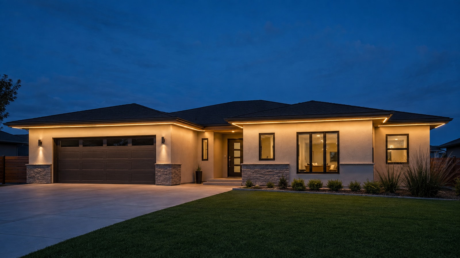
An eave or roofline project should not be ordered as one total reel length and one total wattage. The route must be divided into physical sections, electrical branches, controller outputs, and serviceable installation zones. Only then can buyers calculate strip quantity, driver load, branch current, voltage drop, cable, connectors, and spare material.
This guide gives lighting brands, contractors, distributors, and project buyers a practical calculation method without relying on a universal maximum run or an arbitrary power-supply margin.
Quick answer: use five separate calculations
Calculate the project in this order:
- Route length: measure the installed centerline of every elevation and feature.
- Order length: convert the route into valid cut sections, factory lengths, service leads, and approved spares.
- Electrical load: multiply the exact product’s maximum W/m by each powered branch length.
- Branch current and voltage drop: calculate every feed loop, not only the project total.
- Controller capacity: verify outputs, channels, pixels, refresh requirements, and injection limits separately from driver wattage.
| Calculation | Details |
|---|---|
| Route | Input required: Elevation drawing and measured centerline Output used for purchasing: Installed meters by location |
| Cut plan | Input required: Product cut unit, corners, leads and factory-length options Output used for purchasing: Exact production lengths and section labels |
| Load | Input required: Maximum W/m or A/m for the exact model and scene Output used for purchasing: Watts and amps by branch and total |
| Voltage drop | Input required: Cable length, conductor resistance, current and connections Output used for purchasing: Cable size, feed location and injection plan |
| Control | Input required: Protocol, channels/pixel, pixel count and controller limits Output used for purchasing: Controller quantity, output allocation and signal equipment |
Do not use reel length as a substitute for maximum powered run. A 20 m reel may need to be cut into several separately powered branches.
Measure the route along the actual installation centerline
Use elevation drawings, site measurements, or scaled construction documents. Measure the line where the strip or Neon Flex will physically sit, not the building’s approximate perimeter.
Mark:
- each straight section;
- inside and outside corners;
- gaps around downpipes, doors, joints or equipment;
- transitions between elevations;
- changes from concealed to direct-view installation;
- locations where a cable jumper replaces illuminated product;
- controller and driver positions; and
- accessible service points.
Roof pitch and stepped elevations can make plan-view dimensions inaccurate. Confirm inclined lengths on the elevation or at site. For curved Neon Flex routes, measure the route centerline while respecting the product’s minimum bend radius.
Separate illuminated length from cable and dark gaps
Not every part of the route needs illuminated strip. A corner, expansion joint, rainwater pipe, window gap, or inaccessible cavity may be crossed with a cable jumper.
Create a schedule with at least these columns:
| Section ID | Details |
|---|---|
| E1-A | Illuminated length: Project measurement Jumper/lead length: Project measurement Product family: SMD, COB, RGBW, addressable or Neon Flex Cut length: Based on model cut unit Feed point: Left/right/both Notes: First eave section |
| E1-B | Illuminated length: Project measurement Jumper/lead length: Project measurement Product family: Selected product Cut length: Based on model cut unit Feed point: Defined branch Notes: Corner or downpipe transition |
This prevents buyers from paying for illuminated product where a protected cable is more appropriate, and it prevents installers from stretching one strip through an impossible corner.
Convert measured length into valid production sections
LED strip can only be cut at designated positions. Neon Flex and encapsulated strip may also need additional end-cap and cable-exit space.
For every measured section:
- Identify the exact model’s cut interval.
- Decide whether the section will be cut at the factory or on site.
- Round only according to the approved cut rule and design tolerance.
- Add the physical space required for connectors, end caps and lead exits.
- Confirm whether a short dark gap or adjusted start/end position is acceptable.
- Assign a section ID that appears on the drawing, label and packing list.
Do not automatically round every section upward without checking the available space. An extra cut unit may not fit between architectural boundaries.
Define spare quantity from the service strategy
Avoid applying one generic spare percentage to every project. The correct spare quantity depends on:
- number of unique lengths and connectors;
- factory-made versus field-made terminations;
- expected installation damage;
- color and production-bin matching;
- accessibility after completion;
- replacement lead time;
- minimum order and reel format; and
- whether the project will be expanded later.
A useful spare plan may include one replacement for each critical custom length, additional material from the same production batch, spare connectors and end caps, and a documented controller or power component. Agree the quantity during RFQ rather than hiding it inside an unexplained allowance.
Obtain maximum power data for the exact product
Use the model datasheet, not a typical market value. Record:
- input voltage;
- maximum watts per meter or amps per meter;
- test condition and active channels;
- maximum recommended powered length;
- cut interval;
- operating-temperature limits;
- controller or dimming method; and
- any programmed global brightness or current limit.
For RGB, RGBW and addressable products, power varies by scene. Use the maximum approved operating condition. A red-only chase is not a valid basis if the installation can later run all channels at high output.
Calculate power and current branch by branch
For a constant-voltage strip:
Branch power (W) = maximum strip power (W/m) × branch length (m)
Branch current (A) = branch power (W) ÷ strip voltage (V)
The total project load is the sum of all branch loads, but each cable, controller output and connector must be checked against its own branch current.
Illustrative branch example
Assume a selected 24V strip is documented at a maximum of 12 W/m and one powered branch is 5 m:
Branch power = 12 W/m × 5 m = 60 W
Branch current = 60 W ÷ 24 V = 2.5 A
If the project uses six identical 5 m branches, the connected strip load is:
Total strip power = 60 W × 6 = 360 W
This does not mean that one 360 W power supply is automatically correct. The driver arrangement must still satisfy output zoning, manufacturer loading and temperature derating, enclosure conditions, cable distribution, protection requirements, redundancy and service access.
Size the power supply from documented limits
Do not apply an unexplained rule such as “always add 20%” to every driver. Instead:
- Calculate the maximum connected load.
- Select a constant-voltage output that matches the strip voltage.
- Check the driver’s rated load range and output-current limit.
- Apply the manufacturer’s ambient-temperature, case-temperature, input-voltage and installation derating curves.
- Confirm whether the enclosure changes cooling conditions.
- Check inrush, dimmer, controller, overcurrent protection and local electrical requirements.
- Decide whether one larger driver or several distributed drivers provide the better service and cable plan.
A sealed outdoor enclosure can raise the driver temperature. The label wattage cannot replace a thermal review under the intended ambient and mounting condition.
Calculate voltage drop through the complete loop
For a DC branch, a simplified cable calculation is:
Voltage drop = branch current × total loop resistance
If the outgoing and return conductors have the same length and resistance per meter:
Total loop resistance = 2 × one-way cable length × conductor resistance per meter
The complete installed drop also includes connectors, controller outputs, splices, PCB traces, and injection wiring. Use conductor resistance from the actual cable specification and account for temperature when required by the project.
Illustrative voltage-drop example
Using the 2.5 A branch above, assume the calculated outgoing-plus-return cable resistance is 0.10 ohm:
Cable voltage drop = 2.5 A × 0.10 ohm = 0.25 V
For a 24V source, the cable-only drop is approximately:
0.25 V ÷ 24 V × 100% = 1.04%
This is not the final installed result because the controller, connectors, PCB and operating temperature add further resistance. Measure the voltage at the strip input and far end while the approved maximum scene is running.
Decide where to feed or inject power
Power-feed methods include:
- one-end feed for a short approved branch;
- both-end feed when supported by the product and electrical design;
- parallel feeds to several shorter branches;
- intermediate power injection for compatible addressable products; and
- distributed drivers located closer to the loads.
There is no universal injection distance. Choose the method from branch current, PCB capacity, connector rating, cable resistance, voltage tolerance, product instructions, controller topology, and service plan.
When multiple supplies or injection circuits are used, follow the controller and strip manufacturer’s grounding, common-reference, isolation and circuit-separation instructions. Do not join power-supply outputs unless the supplies are designed and approved for that operation.
Keep controller calculations separate from power calculations
An addressable strip may fit within the driver wattage and still exceed the controller’s pixel or refresh capacity.
Record:
- exact IC/protocol;
- RGB or RGBW channels per pixel;
- controlled pixels per meter;
- total pixels per branch and output;
- data-only or data-plus-clock wiring;
- maximum pixels and current per controller output;
- desired refresh or effect speed;
- data cable distance; and
- required signal receiver, amplifier or differential link.
For example, RGB pixels use three control channels per pixel and RGBW pixels use four. This changes mapping capacity even if the physical strip length is the same.
The RGBIC LED Strip Buying Guide provides the controller fields buyers should request.
Build a roofline power schedule
| Branch | Details |
|---|---|
| B1 | Product/model: To be confirmed Length: Measured Max W/m: Datasheet Branch W: Calculated Voltage: Model voltage Branch A: Calculated Cable length: Measured Feed method: One end/both/parallel Controller output: Assigned |
| B2 | Product/model: To be confirmed Length: Measured Max W/m: Datasheet Branch W: Calculated Voltage: Model voltage Branch A: Calculated Cable length: Measured Feed method: Defined Controller output: Assigned |
Add columns for far-end measured voltage, connector type, protective device, enclosure, section labels, and test result when the electrical designer or local regulation requires them.
The schedule should match the elevation drawing. Every physical section, cable, driver and controller output should be traceable by ID.
Account for outdoor enclosures and cable routes
Outdoor calculations are affected by installation details:
- long cable detours around waterproof boundaries;
- additional connectors and glands;
- higher ambient temperature inside sealed boxes;
- low temperature and material stiffness;
- UV and weather exposure;
- accessible versus concealed junctions; and
- voltage drop after future replacement connectors are added.
Place drivers and controllers where their environmental ratings, cooling, cable distances and maintenance needs can be met. A waterproof strip does not make the rest of the electrical system waterproof.
Validate the calculation with a representative test
Before production release, assemble the longest or most demanding branch with the intended strip, cable, connectors, controller, driver and sealing method.
Measure:
- source voltage with no load and under load;
- voltage at the branch input and far end;
- branch current in the maximum approved scene;
- controller and connector temperature;
- visible brightness and color from beginning to end;
- addressable stability and color accuracy; and
- behavior after start-up, dimming and power cycling.
If the measured result differs from the calculation, update the cable, branch length, feed plan, connection method, driver location, or product choice. Do not adjust the design only by raising output voltage beyond the strip or controller specification.
RFQ checklist for length and power planning
Send:
- Scaled elevations or measured route drawings.
- Illuminated sections, dark gaps, corners and cable jumpers.
- Candidate strip family and model, if known.
- Cut interval, factory-cut requirements and lead directions.
- Maximum W/m or A/m and operating scene.
- Total length and longest proposed powered branch.
- Driver and controller locations.
- Cable length, conductor specification and connector type.
- Power-feed or injection proposal.
- Pixel protocol, density and controller-output allocation.
- Outdoor exposure, enclosure and sealing requirements.
- Spare sections, labels, packaging and first-article test plan.
Review Wismart product and calculation inputs
Start from the Wismart LED strip product directory, then compare the relevant SMD Strip Lights, Silicone Strip Lights, LED Neon Flex, or Addressable / Programmable SMD route.
Send the measured schedule, voltage, color/control requirement, cable distances, exposure and quantity through the roofline power-planning inquiry form. Wismart can identify the relevant product datasheet and prepare a model-specific sample for calculation verification.
Frequently asked questions
How much extra LED strip should be ordered?
There is no universal percentage. Convert each route into valid cut sections, then add documented custom-length replacements, same-batch spares, connectors and end caps according to the service plan.
Can total watts determine the power-supply size?
Total connected load is only the starting point. The selected driver must also meet voltage, current, loading range, temperature derating, enclosure, control, protection and installation requirements.
Is a 24V strip always suitable for twice the run length of 12V?
No. At equal power it draws half the current, but maximum run also depends on the PCB, LED grouping, connector, cut unit, thermal conditions, brightness tolerance and feed method.
How often should addressable strip receive power injection?
Use the exact strip, controller and cable data. Determine injection points from current, voltage drop, PCB and connector limits, measured performance and manufacturer instructions, not a fixed meter rule.
Should voltage be measured at the driver or the strip?
Measure both. Driver-terminal voltage does not include the drop through cable, controller, connectors and splices. Also measure the far end under the approved maximum load.
Conclusion
Accurate roofline ordering requires a route schedule, cut plan, branch load calculation, voltage-drop review, controller allocation and representative test. Measure and label each physical section, calculate every electrical branch, apply the actual equipment limits, and verify the longest branch before bulk production.