
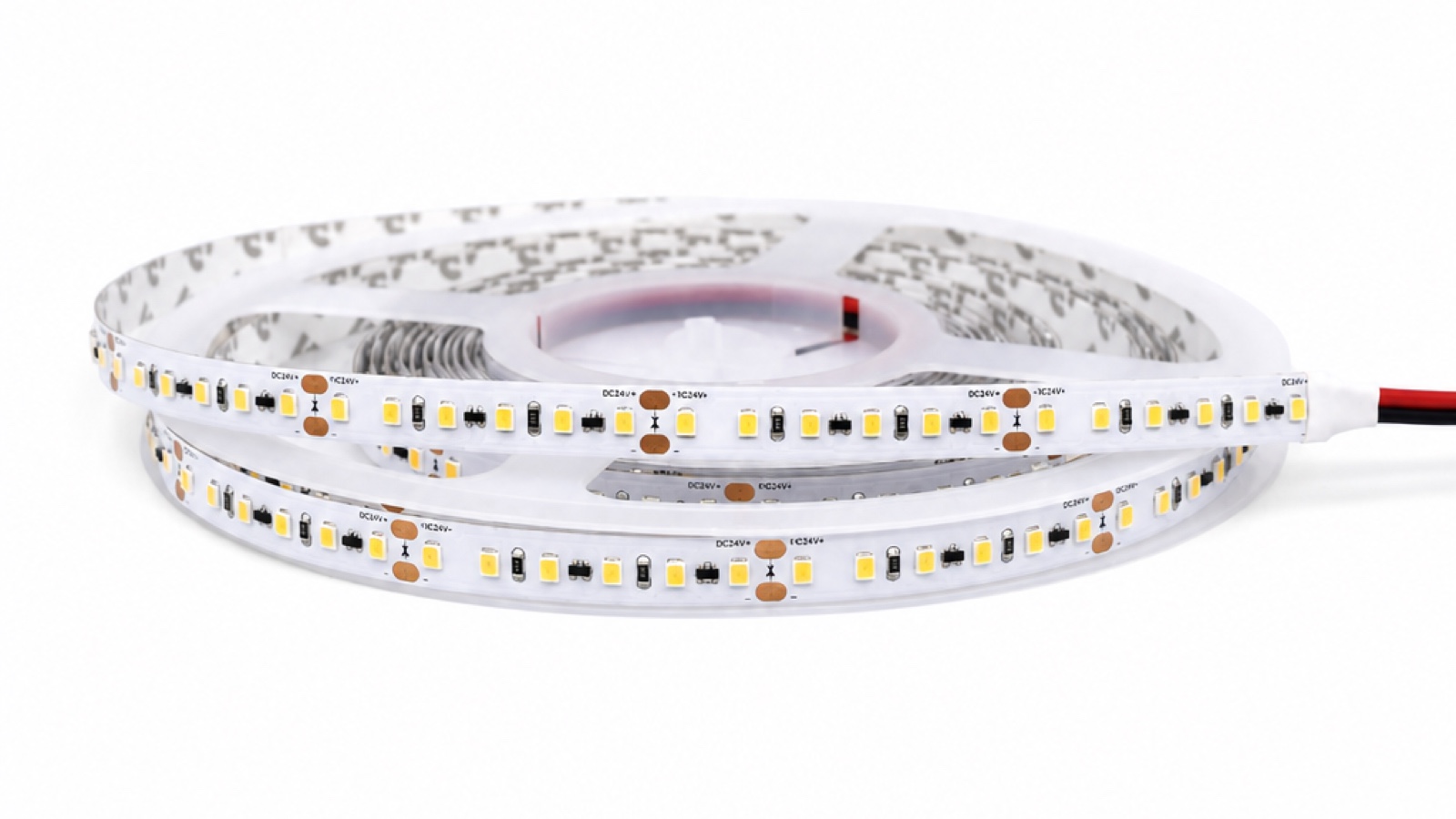
For LED strip buyers, the power supply and wiring plan decide whether the installed line reaches its intended output, dims correctly and avoids dark ends, color shift, nuisance shutdown or premature component stress. The correct driver is not selected by wattage alone.
This B2B guide explains how to choose an LED strip power supply and avoid voltage drop by matching the strip voltage, actual load, driver data, conductor route, feed arrangement, controls, environment and certification requirement.
Quick answer for LED strip power planning
| Decision | Purchasing action |
|---|---|
| Output type | Use a compatible constant-voltage driver for a constant-voltage strip, and match the rated output voltage exactly. |
| Driver capacity | Calculate the real connected load, then apply the selected driver's loading, ambient, enclosure and derating requirements. Do not rely on one universal headroom percentage. |
| 12V or 24V | At equal power, 24V draws about half the current of 12V and is often easier to manage for resistive drop. It does not create a universal maximum run. |
| Voltage drop | Calculate and test the complete loop: feed cable, strip copper, connectors, controller and return path. |
| Dimming | Validate the driver, dimmer/controller, strip load and protocol as one system, including low-end behavior and flicker. |
| Approval | Build the longest or most electrically demanding representative section and measure voltage, output, temperature and controls before bulk order. |
Start by matching the strip's rated voltage
Most conventional flexible LED strips are constant-voltage loads with local resistors or current-regulation components. The driver output must match the strip's rated input. A 24V strip requires a compatible 24V constant-voltage supply; it should not be connected to a 12V or 36V output.
| Voltage route | Procurement implication |
|---|---|
| 5V | Common in short specialty or addressable systems; current and injection planning become critical quickly. |
| 12V | Useful for short fixtures, cabinets and small signs where cut-section or existing-system requirements support it. |
| 24V | A practical starting point for many commercial shelves, coves and longer low-voltage runs because equal power requires less current than 12V. |
| High-voltage or dedicated system | Treat as a separate matched system with its own product, accessories, protection, certification and qualified installation requirements. |
Do not choose voltage from project length alone. Confirm the exact strip family, cut interval, control method, available driver, cable route and local electrical requirements.
Calculate the connected load before selecting the driver
For a uniform single-color strip, the basic strip load is:
Strip load (W) = rated watts per meter × installed meters
Add any controller, receiver or other load that is powered from the same supply according to its documentation. For RGB, RGBW, tunable-white or addressable systems, use the manufacturer's specified worst-case channel/load condition rather than assuming every effect draws the same power.
The final driver rating should follow the exact driver's permissible loading and derating data. Ambient temperature, enclosure, ventilation, input voltage, mounting, control mode and continuous operating condition can change the usable capacity. A fixed “load × 1.2” or “load × 1.25” rule is not a substitute for the driver datasheet.
Check current as well as watts
For a DC load, the first-order current calculation is:
Current (A) = power (W) ÷ voltage (V)
A 120W load draws about 10A at 12V or 5A at 24V before considering product tolerances and other system loads. Lower current reduces the voltage lost across the same resistance and reduces conductor heating, which is why 24V is often easier to route for longer commercial sections.
Controller output ratings, connector ratings, cable capacity, protection devices and terminal limits must also cover the real channel and total currents. Watts alone can hide an overloaded connector or controller channel.
Understand where voltage drop occurs
Voltage drop follows the relationship Vdrop = current × total loop resistance. The loop includes the outgoing and return conductors, and the installation also includes resistance inside strip copper, connectors, solder joints, controller outputs and distribution points.
| Resistance source | What the buyer should confirm |
|---|---|
| Driver-to-strip cable | One-way distance, complete loop length, conductor material, cross-section, bundling and ambient conditions. |
| Flexible PCB copper | Exact strip model, watts per meter, feed direction and model-specific maximum permitted length per feed. |
| Connectors and joints | Current rating, contact quality, environmental sealing and whether factory leads are preferred. |
| Controllers and receivers | Total and per-channel current limits, terminal limits and voltage loss under the required load. |
| Distribution layout | Parallel branches, fuse/protection arrangement, feed points and service access. |
The acceptable drop is project-specific. It depends on the strip's operating range, visible brightness tolerance, color behavior, run geometry and design criteria. Measure the beginning and end of the representative section rather than applying a generic distance table from another product.
12V versus 24V for voltage-drop control
| Project condition | Selection direction |
|---|---|
| Short fixture with a required short cut section | 12V may fit if the exact model, load and feed route pass the mock-up. |
| Longer shelf, cove or commercial line | Review 24V early because equal power uses lower current, then verify the model-specific run limit. |
| Remote driver location | Prioritize conductor calculation and feed architecture; 24V may help but cannot replace correct cable sizing. |
| RGB/RGBW or tunable-white system | Check controller channel ratings, common conductor loading, injection method and protocol compatibility. |
| Existing 12V infrastructure | Confirm whether reusing it meets load, certification, dimming and voltage-drop requirements before locking the strip. |
There is no universal statement that a 24V strip can run a fixed number of meters. Power per meter, PCB design, current regulation, allowable variation, feed arrangement and manufacturer limits determine the answer.
Use a feed layout that matches the selected product
Long visual lines are often divided into shorter electrical branches even when the light appears continuous. Parallel feeds can reduce the current carried through upstream strip sections. Larger conductors or a closer driver may reduce cable drop. Multiple drivers or distribution points may improve serviceability and zoning.
Feeding both ends or adding intermediate injection can be useful for some products, but it is not a universal instruction. Confirm polarity, controller topology, grounding/common-conductor arrangement, protective devices and the strip manufacturer's connection guidance. Incorrect injection can damage equipment or create unsafe fault paths.
- Do not daisy-chain beyond the selected model's permitted feed length.
- Do not assume every quick connector can carry the required current.
- Do not hide inaccessible joints or drivers without a maintenance plan.
- Do not use a higher driver output voltage to “compensate” for drop unless the exact system documentation explicitly permits adjustment and the strip terminals remain within limits.
Select the power supply for environment and compliance
| Installation condition | Driver questions |
|---|---|
| Dry indoor cabinet or shelf | Approved mounting method, ventilation, touch protection, plug/terminal arrangement and service access. |
| Commercial cove or ceiling void | Ambient and enclosure derating, fire/safety requirements, cable route, access and dimming compatibility. |
| Outdoor sign or facade | Exact IP/environment rating, cable glands, drainage, temperature range, surge strategy and enclosure details. |
| Export program | Model-specific safety and EMC files, target-market approvals, labeling, input range and warranty conditions. |
An IP-rated strip does not make an indoor driver suitable outdoors. Each driver, controller, junction and cable entry must be selected for its own installed environment. Final mains wiring and compliance should be handled by qualified personnel.
Treat dimming as a driver-controller-strip system
Terms such as phase-cut, 0-10V, DALI, DMX and PWM describe different parts of a control chain. They are not automatic properties of every LED strip. A DALI project, for example, normally needs a compatible driver or controller with the required load and output behavior.
- Confirm the input/control protocol and the driver's output method.
- Check the driver's permitted load range and the controller's total/per-channel current.
- Test minimum dimming level, turn-on behavior, flicker, noise and synchronization.
- Use the actual cable lengths and representative connected load.
- For cameras, museums or other sensitive applications, align flicker requirements with the project specifier and measurement method.
Build a representative power and voltage-drop sample
| Test | What to verify |
|---|---|
| Longest electrical section | Build the most demanding planned feed, not only a short display sample. |
| Voltage measurement | Measure driver output, strip input and the critical far point at the required operating condition. |
| Visual uniformity | Compare brightness and color along the run at normal viewing positions. |
| Driver and controller | Test the exact models, channel loads, dimming range, startup and fault behavior. |
| Thermal condition | Use the intended profile, enclosure and representative ambient condition, then compare with component limits. |
| Connections | Inspect terminals, connectors, joints, cable entries and protective devices under the real current. |
RFQ checklist for LED strip and power supply planning
| RFQ input | Information to send |
|---|---|
| Strip specification | Product family/model, rated voltage, watts per meter, CCT/color/control route and required output. |
| Layout | Total meters, individual section lengths, longest feed, drawing and driver locations. |
| Cabling | Driver-to-strip distances, conductor material/cross-section, connector and distribution plan. |
| Power supply | Input range, output voltage, planned load, environment, enclosure and target-market approvals. |
| Controls | Protocol, dimmer/controller model, zones, channel loads, low-end target and flicker requirement. |
| Installation | Profile/mounting, ambient range, indoor/outdoor exposure, service access and qualified-installation requirements. |
| Commercial scope | Sample plan, quantity, destination market, compliance documents, packaging and labeling. |
Review Wismart strip routes before finalizing the power plan
Start from the Wismart LED Strip Product Center, then compare COB Strip Lights and SMD Strip Lights. Wismart's current product routes include multiple low-voltage families and project-specific long-run options, but the maximum feed length, power and wiring plan must come from the selected model's current specification.
Use the COB Strip Light Catalog and SMD Strip Light Catalog to shortlist the strip family. Then send the real layout, section lengths, cable distances, controls and target market through the power-supply and voltage-drop review form to request the matched datasheet, sample and quotation.
Frequently asked questions
How much spare driver wattage should a buyer add?
There is no universal percentage for every driver. Calculate the real connected load, then follow the selected driver's loading, ambient, enclosure, input and derating requirements. Include controller or accessory loads where they share the supply.
Does 24V eliminate voltage drop?
No. At equal power it reduces current compared with 12V, which usually reduces resistive loss for the same conductor. Cable resistance, strip copper, connectors, controllers and feed length still create drop and must be calculated and tested.
Can every long strip be fed from both ends?
No. Confirm the product's connection instructions, polarity, controller topology, protective devices and common-conductor arrangement. Feeding both ends is one possible design method, not a universal field instruction.
Is a waterproof driver required for an outdoor strip?
The driver and every connection must suit their own installed environment. A driver may be located in a properly designed dry enclosure or may need an appropriate environmental rating. The strip's IP rating does not protect the driver automatically.
Conclusion
The right LED strip power supply is selected by matching voltage, real load, driver limits, environment, controls and compliance. Voltage drop is controlled by the entire current path, including cable, strip, connectors and controllers. A representative measured mock-up is the strongest approval step before bulk purchasing.
Review Wismart COB and SMD strip options, download the relevant product catalog, and request a matched specification, sample and quotation using the real electrical layout.